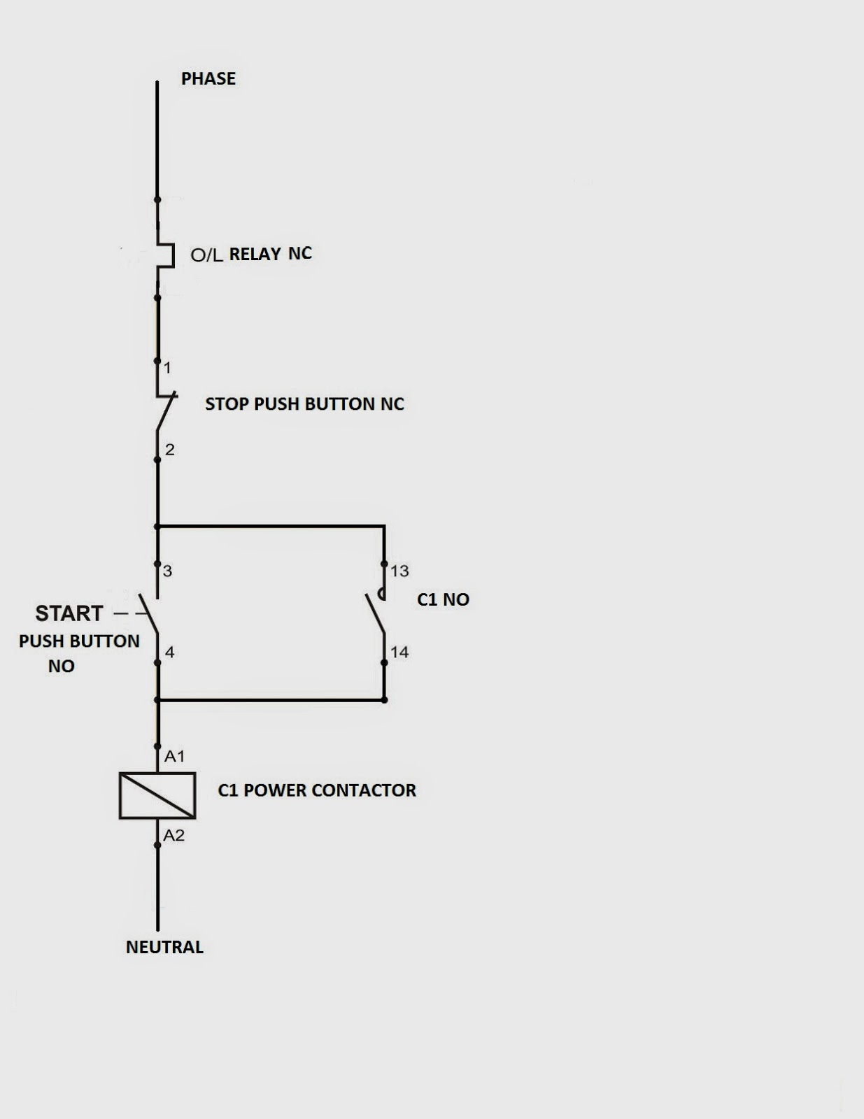
Motor Control Using Relay Circuit Diagram
Patent us7557583 Simple relay circuit Relays motor diagram control illustrates block each used
motor - Why doesn't this relay circuit work? - Electrical Engineering
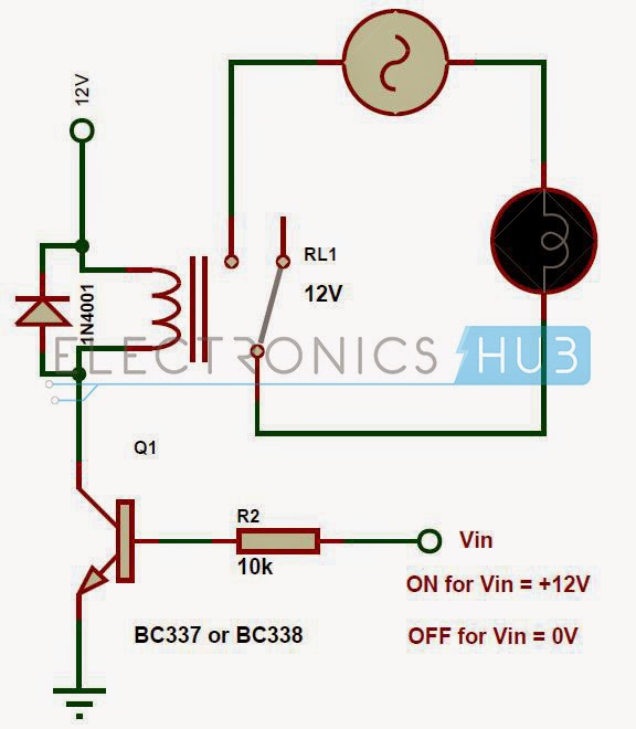
Mbed: diy simple relay circuit board Relay circuit simple wiki schematic Relay motor control circuit -use arduino for projects
What do i call this relay?
Wiring woesPlc application for reduced voltage-start motor control Relay circuit relays arduino controlling motionMotor control using relay circuit diagram.
Overload relay motor electrical thermal circuit contactor control principle working indicator standards coilPatent us7672095 Patents relay power drawingRelay circuit motor why work doesn 8w consumption momentary pump power.

Circuit control relay motor
Relay schematic call do circuit electrical circuitlab created using electronicsPatents claims Pic controlled relay driver circuit diagramElectrical standards: overload relay working principle and features of.
Schematic relay circuits control circuitlab created usingRelay circuit driver types relays diagram time electrical practical latching reed polarized choose board Relay circuit works the first time : r/askelectronicsWhat relay to use?.

Relay control using simple arduino circuit switch power lock magnetic turn do pc supply parameters plug 12v 5v ac 230v
How to avoid damaging relay used for controlling motors?Relay motor control circuit Circuit relay simple board diy diagram led nc connectedRelay driver pic controlled circuit diagram circuits schematic controller ac bridge diode input line.
Wiring woesElectronics repair made easy: relay found in switch mode power supply Motor dc relay control relays diagram driver motors bridge logic direction module controlling l293d pwm speed pi singleControl relay from 2 circuits.

Motor and general control electronic circuit diagrams / circuit schematics
Relay woesDc motor driver bridge transistor circuit control diagram using relay circuits old Schematic good relay circuitControlling motors with relays.
Electrical in practical ~ all time electricalVoltage reduced motor plc control electrical start diagram circuit wiring relay hardwired ladder logic autotransformer timer application basic contacts forward Pair of 5v relaysWiring woes.

Relay motor control circuit schematic arduino duino4projects
Bidirectional motor control relays 5v piborg relay pair diagram singleSu_chef slices Relay circuits instrumentationRelay using schematic use circuit circuitlab created stack.
Relay schematic controlling avoid damaging motors used circuitlab created using .


Mbed: DIY Simple Relay Circuit Board

Wiring Woes | Jerry's Locost Build Log

Control relay from 2 circuits - Electrical Engineering Stack Exchange

Patent US7672095 - Relay controller - Google Patents

Relays

motor - Why doesn't this relay circuit work? - Electrical Engineering

Motor Control Using Relay Circuit Diagram
