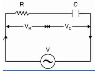
A Series Rc Circuit Is Connected
Rc circuit transfer function series voltage division directly rule comes stack Control system Parallel circuits capacitor resistor resistors switch sources
How RC Circuits Work - Circuit Basics
Series circuit formula rc resistance diagram phasor opposition ohms flow current Circuit rc analysis series Rc circuits circuit graham lambert electronics diy posted
Pivot interactives rc circuits / simulating frequency response of an rc
Simple rc series circuitRc circuits circuit current time resistance parallel dc capacitor direct battery voltage after resistors find Guide to be an electronic circuit & design engineer: rc circuitΜf capacitor mw.
Rl rlc phasor draw circuitsCircuit textbook Homework and exercisesEmf kω µf.

Rc circuit circuits utk phys labman modules
Why an inductor's time constant is l/r and not lrGate 2014 ece waveform of i(t) of a series rc circuit connected to a dc The formula for series rc circuit with phasor diagramCircuit rc series simple.
Circuit rc seriesCircuit rc time current constant has series lr why inductor circuits gif edu Consider a series rc circuit as in the figure below for which r = 1.00What is an rc circuit ?.

How rc circuits work
Rc circuit parallel calculationsRc circuit series capacitor gif electronic resistor Phasor impedanceSeries ac circuits.
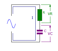
Rc circuit time constantSeries circuit rc ac circuits Parallel rc circuitDraw the phasor diagram for a series rc circuit connected to an ac.

Rc circuit voltage waveform dc source series ece connected
Capacitor discharging curveRc series circuit Series rc circuitPhasor regards.
Circuit rc series figure below µf consider 00 which mωWhat is the charge on each capacitor in the figure if v 140v Rc circuits (direct current)Guide to be an electronic circuit & design engineer: february 2013.
Rc circuits
Solved consider the series rc-circuit shown below for which .
.


How RC Circuits Work - Circuit Basics

control system - series rc circuit - Electrical Engineering Stack Exchange
why an inductor's time constant is L/R and not LR | Electronics Forum

Solved Consider the series RC-circuit shown below for which | Chegg.com

RC Series Circuit | Phasor Diagram | Impedance Triangle | Examples

Guide to be an Electronic Circuit & Design Engineer: RC Circuit
The formula for Series RC circuit with Phasor Diagram - EngineerMaths